Device documentation
I/O mapping for Altera DE1-SoC
By: WebLab-Deusto (University of Deusto) , Giovanna Lani (WebLab-Deusto, University of Deusto)
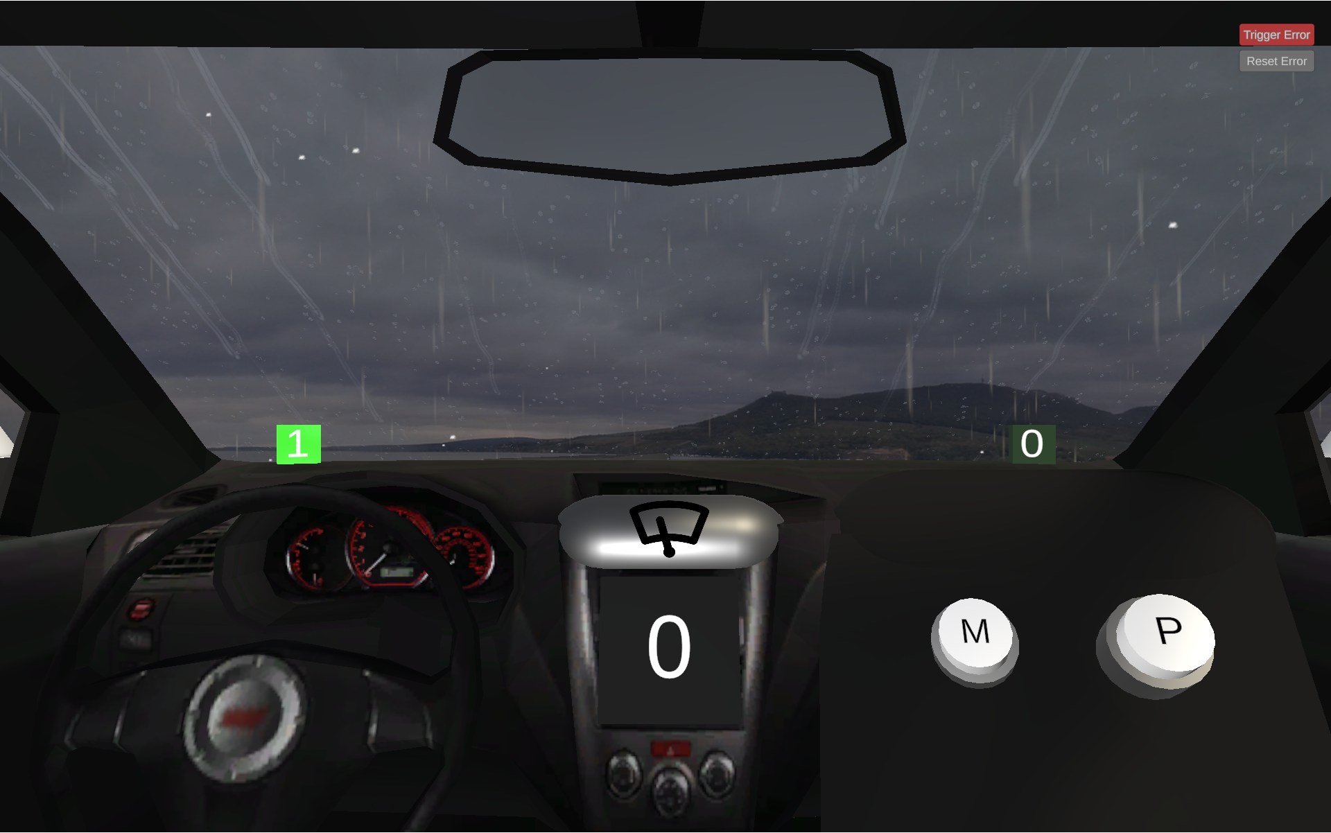
Wiper (one-bit) DE1-SoC I/O mappings
All signals are active high. GPIO numbers refer to the LabsLand virtual GPIO
bus; in VHDL, for example, GPIO 28 is V_GPIO(28).
| Runtime signal | Meaning | Type | GPIO |
|---|---|---|---|
rainSensor |
Rain is active | FPGA input | GPIO 28 (V_GPIO(28)) |
rightSensor |
Wiper is at the right-hand limit (minimum angle) | FPGA input | GPIO 29 (V_GPIO(29)) |
leftSensor |
Wiper is at the left-hand limit (maximum angle) | FPGA input | GPIO 30 (V_GPIO(30)) |
mButton |
The interface's M button is being pressed | FPGA input | GPIO 23 (V_GPIO(23)) |
pButton |
The interface's P button is being pressed | FPGA input | GPIO 24 (V_GPIO(24)) |
move |
Enable wiper movement | FPGA output | GPIO 26 (V_GPIO(26)) |
When move is high, the simulation moves the wiper and reverses its direction
automatically at each endpoint. When move is low, it stops at its current
position. Between the endpoints, both endpoint sensors can be low. The
simulation's error control deliberately makes both endpoint sensors high so
that controller error handling can be tested.