Device documentation
I/O mapping for STM32 Nucleo WB55RG
Wiper 2-Bit STM32 Nucleo WB55RG
By: WebLab-Deusto (University of Deusto) , Giovanna Lani (WebLab-Deusto, University of Deusto)
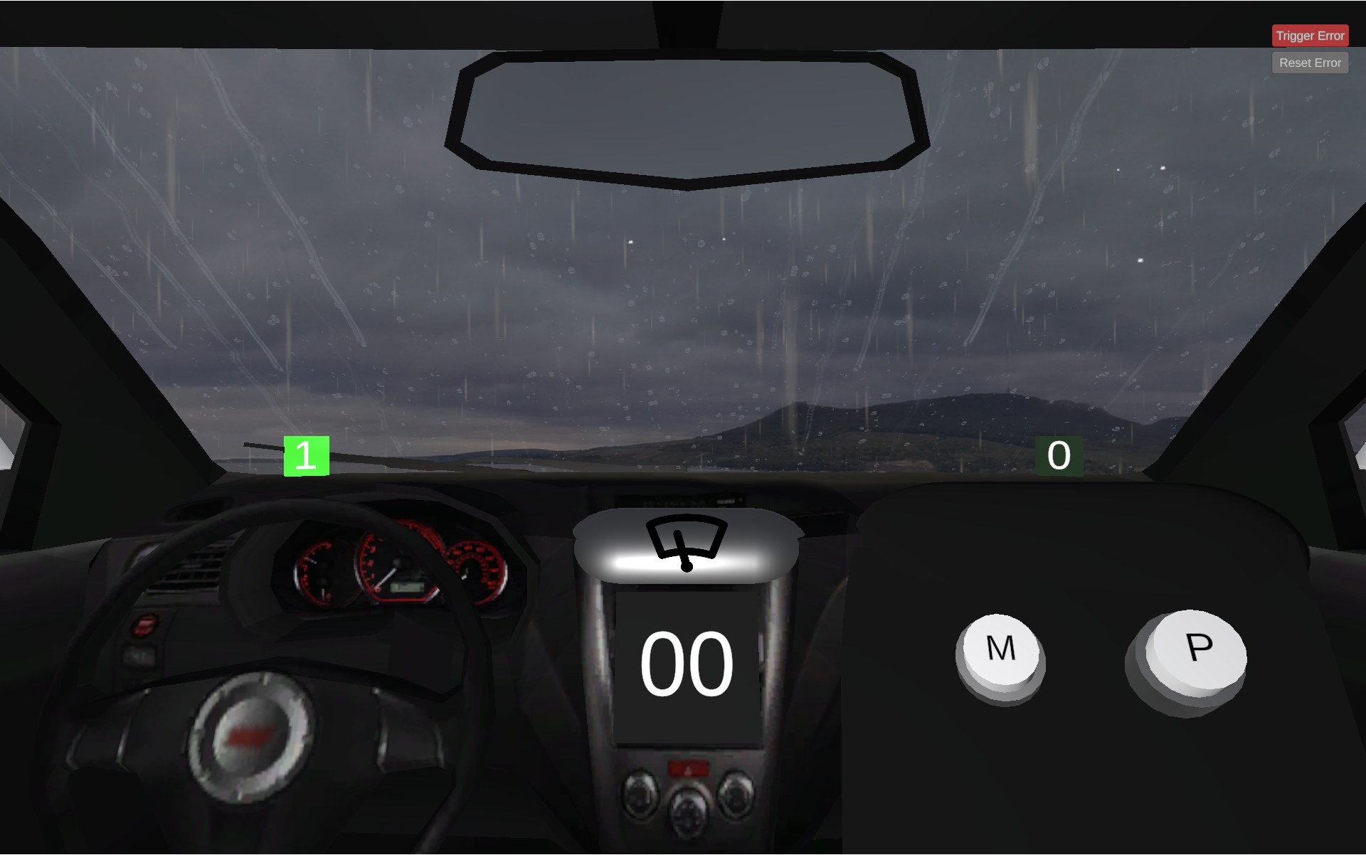
Wiper (two-bit) STM32 Nucleo WB55RG I/O mappings
All signals are active high. The direction shown is relative to the STM32.
| Runtime signal | Meaning in the current simulation | Type | GPIO | STM32 HAL name |
|---|---|---|---|---|
rainSensor |
Rain is active | STM32 input | PC_13 | GPIOC, GPIO_PIN_13 |
rightSensor |
Wiper is at the left-hand limit | STM32 input | PA_6 | GPIOA, GPIO_PIN_6 |
leftSensor |
Wiper is at the right-hand limit | STM32 input | PB_9 | GPIOB, GPIO_PIN_9 |
mButton |
The interface's M button is being pressed | STM32 input | PB_8 | GPIOB, GPIO_PIN_8 |
pButton |
The interface's P button is being pressed | STM32 input | PC_12 | GPIOC, GPIO_PIN_12 |
move1 |
First movement-control signal | STM32 output | PC_4 | GPIOC, GPIO_PIN_4 |
move2 |
Second movement-control signal | STM32 output | PD_0 | GPIOD, GPIO_PIN_0 |
The command pair is written in (move1, move2) order:
move1 / PC_4 |
move2 / PD_0 |
Result |
|---|---|---|
| 0 | 0 | Stop |
| 0 | 1 | Move toward the right-hand limit |
| 1 | 0 | Move toward the left-hand limit |
| 1 | 1 | Error state |
The current two-bit simulation publishes the endpoint channels with their
runtime names reversed: rightSensor reports the physical left-hand limit and
leftSensor reports the physical right-hand limit. This is different from the
one-bit Wiper. Use the endpoint meanings in the table above when implementing a
controller. Between the endpoints, both endpoint sensors can be low.