-
Altera DE1-SoC
- VHDL
- Verilog
- SystemVerilog
-
STM32 Nucleo WB55RG
- STM32CubeMX
- mbedOS
- Online IDE (STM32CubeMX)
KeyPad documentation
General explanation of how this simulation work
Download Word version Download Markdown versionKeypad
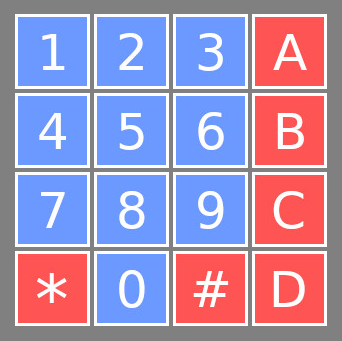
The keypad has 4 inputs (from the keypad perspective) and 4 outputs (from the keypad perspective).
The 4 inputs are 4 rows:
- Row 1: top row
- Row 4: bottom row
The 4 outputs are the 4 columns:
- Column 1: left column
- Column 4: right column
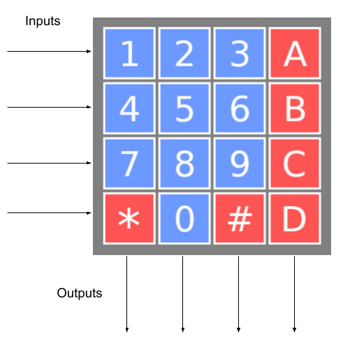
Your device should be sending a '0' to all the rows except for one, and then you can collect the data of the 4 columns with the 4 outputs.
For example, to figure out if the button 6 is pressed, you have to activate the second row, by sending the following signals to the keypad inputs: 0, 1, 0, 0. Once you do it, and wait a bit (e.g., 1ms) for the keypad to adjust, it will return which buttons in the second row are pressed. For example, it might answer 0, 0, 0, 0 (no button pressed), 1, 0, 0, 0 (button "4" pressed), 0, 0, 1, 0 (button "6" pressed).
If you want to constantly monitor which buttons are on, you have to sequentially send the signals 1, 0, 0, 0, 0, 1, 0, 0, 0, 0, 1, 0, and 0, 0, 0, 1.
This is a digital twin of the Parallax 4x4 Matrix Membrane Keypad.